How To
This represents a guide on different themes about configuring in TWW.
Setting default values
If you get the following error message on startup of the TEKSI project during the ‘Database production ready check’:
Warning
fk_provider or fk_dataowner not set in tww_od.default_values
then your database is not yet production ready.
It is possible to define default values for repeated fields such as fk_provider or fk_dataowner, so that you not have to add those manually for each object that you are creating.
There is a new layer group ‘configuration’ in the project:
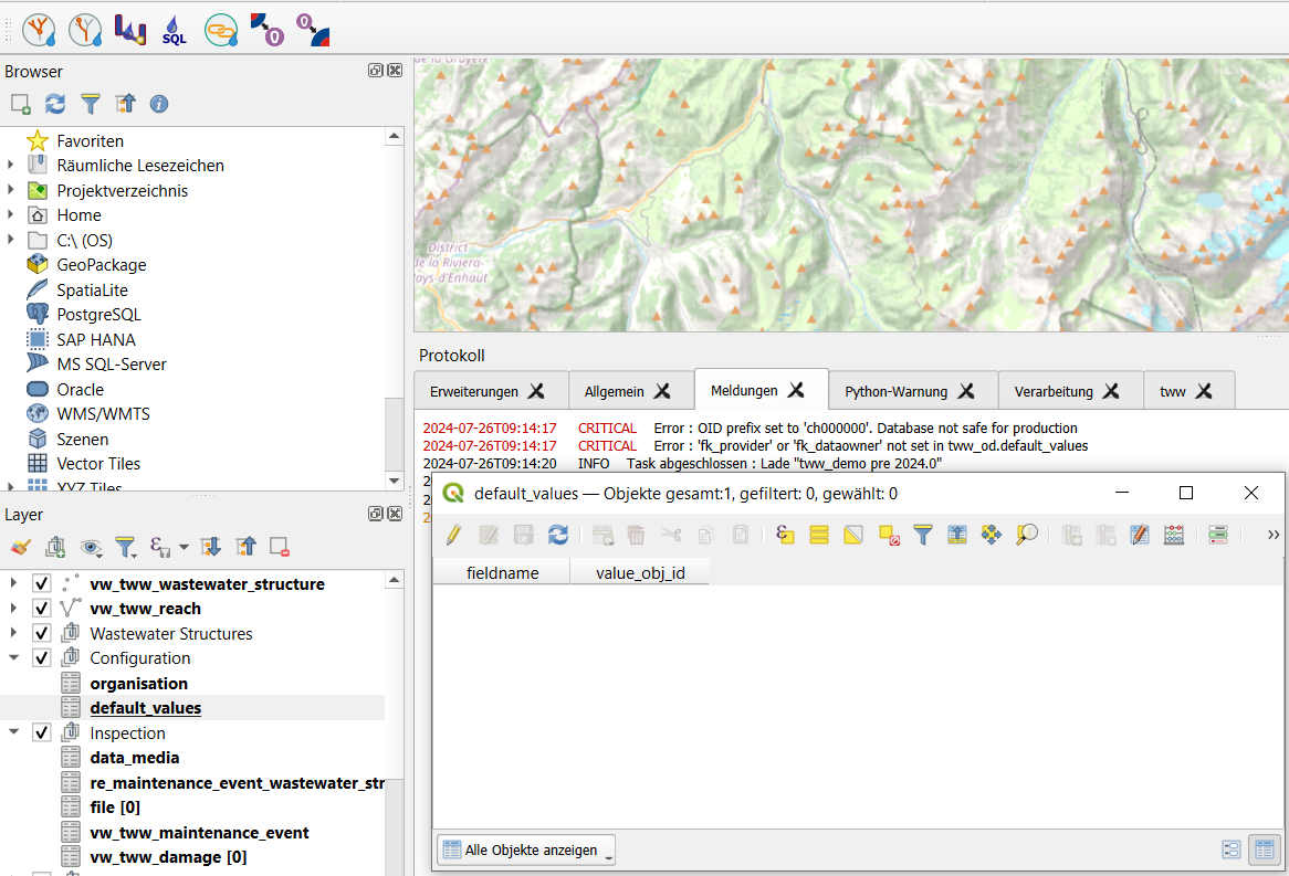
Open the attribute table ‘Default values’
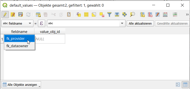
Change to edit mode and choose select new object
Select field name (currently fk_dataowner and fk_provider are supported in the form)
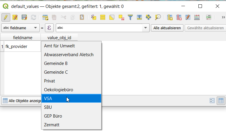
Select organisation that should be used (the corresponding obj_id will be added in the table itself).
Note
If you do not have any organisations you first have to import them with the `Interlis Import chapter
<https://teksi.github.io/wastewater/admin-guide/interlis-io/index.html#interlis-import>`_
For the second warning, please contact your TEKSI system administrator
Warning
CRITICAL: Error OID prefix set to ‘ch000000’. Database not safe for production.
and ask him/her to set the prefix to fit your project.
For more information see Prepare database for production
Connect all occurences of your field name to tww_app.get_default_values(field_name).
Per default, the fields fk_provider and fk_dataowner are already connected to the function tww_app.get_default_values(field_name).
An example SQL script how to insert the default value for all occurences of a field name can be found here)
Increase speed of calculations and update symbology and labels
The TWW plugin has some menu commands to speed up calculations and for updating symbology and labels.
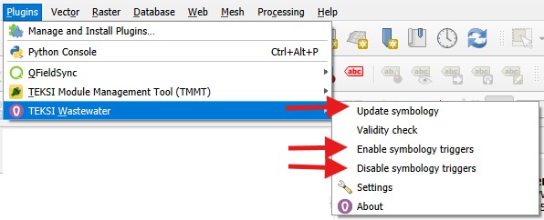
Select Disable symbology triggers before starting multiedit or a field calculation for a change of many records.
Select Enable symbology triggers after the calculations or the multiedit sessions. If you forget to enable the symbology triggers, TWW will warn you if you start the project the next time.
When the triggers are disabled, there is no update of calculated fields. E.g. the input- or output-labels or the _channel_function_hierarchic field in in layer vw_tww_wastewater_structure are not recalculated. To recalculate all these fields select Update Symbology in the TWW-Plugin-menu
Working with labels
How vw_tww_wastewater_structure labels work
Labeling a manhole with his levels is quite a complex thing. Levels are not stored in the wastewater_structure class itself, but in the cover table and as reachpoint levels with the connected reaches. TWW has therefore 4 calculated fields to be able to label these levels:
_cover_label: shows the level / the levels of the cover/s.level of the wastewater structure
_bottom_label: shows the level / the levels of the wastewater_node(s).bottom_level of the wastewater structure
_input_label: shows the levels of the reachpoints connected as to_reachpoints to one of the wastewater_nodes of the wastewater_structure
_output_label: shows the levels of the reachpoints connected as from_reachpoints to one of the wastewater_nodes of the wastewater_structure
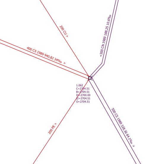
In this example, there are 4 input-reaches to the manhole, but there are only two input-labels (I1, I2). Why?
Answer: in the function, where the _input_label is calculated, can be set a filter so that only reaches with specified function_hierachic (e.g. only pwwf-reaches) are labeled (uses a specific field in the vl-channel_function_hierarchic, documentation follows). In the example, the 200mm-reaches are swwf-reaches and therefore not labeled.
Which reach is I1, which is I2?
Answer: TWW uses the azimut of the last segment of the reach (for inputs) or the first segment of the reach (for outputs) to define the order of the labels. If you stand on the Main-Node of the manhole and turn to the outlet, you find first I1 if you turn clockwise and you find later I2. In the example, 400 wastewater-reach is I1, 300 combined-wastewater-reach is I2.
Hint
This way of numbering the reaches differs from QGEP, where the north direction was the starting point.
How to translate a label prefix (C, B, I, O)
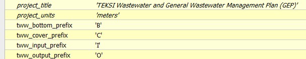
To easily translate label prefixes a series of QGIS project variables have been added. If you want to change the prefixes for cover level, bottom level and entry and exit levels, change the following project settings:
To see your changes, you have to choose “Update Symbology” in the TWW-plugin menu.
Manual Label-positioning for different scales
QGIS label definition can handle different labels for different scales. This works very well if you work on the screen. If you have to print plans with labels or if you have to export labels for data exchange (e.g. exchange with RegioGIS-platform), it will often be necessary to determine the label positions manually. If a label is positioned manually in QGIS, this fixed position applies to every scale. And that’s not always a good result.
Solution
Extend the Auxiliary Storage File with new fields for different labelpositions
Use Rule-based labeling, then you can define different labelpositions for every rule
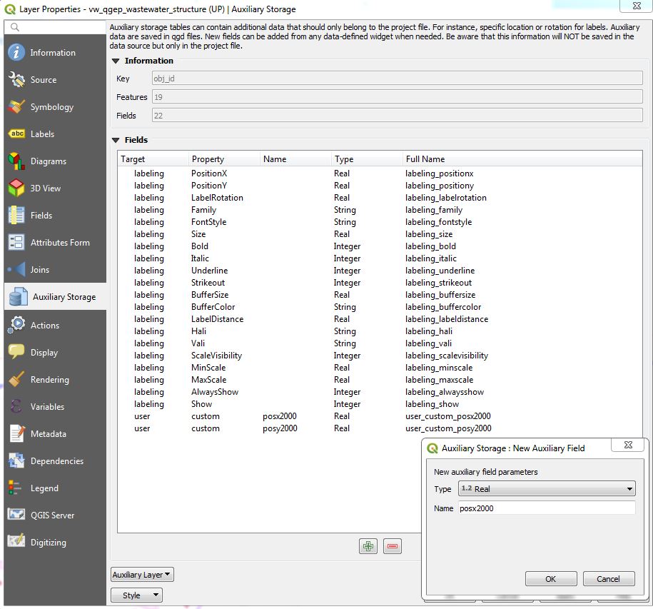
In the example below, we want to label the wastewater-structures with a detailed label for network_plan (1:500) and for overviewmap (1:2000). In the Auxiliary Storage we use the standard fields PositionX and PositionY for the network_plan labels. For the overviewmap labels we add two new fields. We name this fields posx2000 and posy2000.
Define now rule-based labeling with two rules. In the example the first rule is called WP-Labels (WP = Werkplan = network_plan). You have not the change something in the placement, because this rule uses the standard positioning-fields.
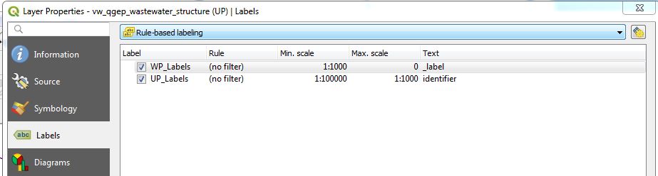
The second rule is called UP-Labels (UP = Uebersichtsplan = overviewmap). In this rule, you have to change the coordinate fields in the placement-tab.
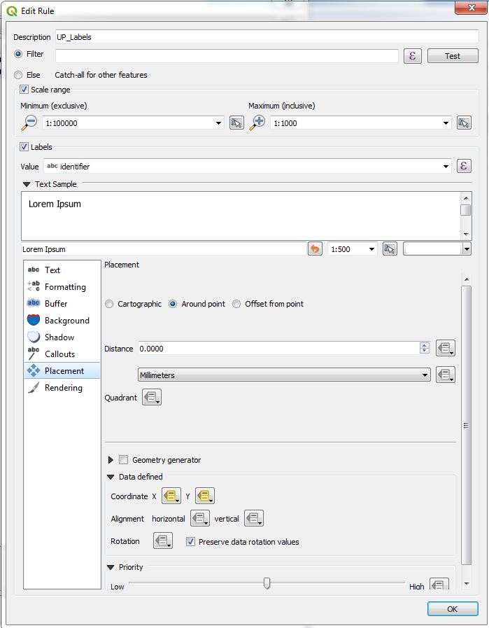
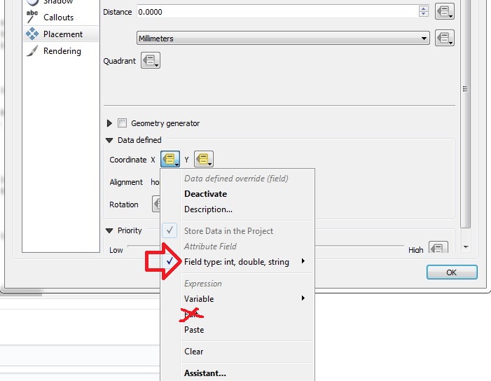
Click on Coordinate X menutool and choose in the field type-menu the auxiliary_storage_user_custom_posx2000 field. Then the similar for Y.
Attention
Do not use the Edit… menu for defining the coordinate-field. If you use a formula or choose the field via the Edit… menu, QGIS will overwrite the definition everytime you do a manual positioning.
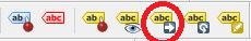
Now you can move or fix your labels for every rule with different positions with the QGIS Moves a Label or Diagram-Tool.
Attention
Your changes are only saved if you save the QGIS-project!
How to import existing label-positions
Good label-positions can be hard work. So you don’t want to loose it.
Export your label-positions from your old system in the form obj_id, coordinateX (east), coordinateY (north).
Add the .qgd-file of your project with Add Vector Layer… to your project and open the attribute table.
If you can not find a .qgd-file, then you have probably not moved or rotated a label before.
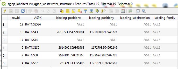
Change the field-names in your export-data to the field-names in the qgd-file. In the example the obj_id-field must have the name ASPK, the coordinate-fields must have the names labeling_positionx and labeling_positiony.
Open the export-file in the QGIS-project and copy the rows you want to the table of the qgd-file (this file must be editable).
Save the qgd-file and remove it from your project, before you remove labels, because QGIS can not save manual label-positions, if the qgd-file is a layer in the project.
If necessary define the horizontal/vertical alignment of your label-coordinates in the placement of the label definition.
Hydraulic modeling
Collecting a hydr_geometry (corresponds to a basin geometry in Mike+)
Note:
Wastewater structures with a hydr_geometry have to be defined as special structures (and not as standard manholes).
The detail geometry can be graphically drawn with the Digitize action.
Action:
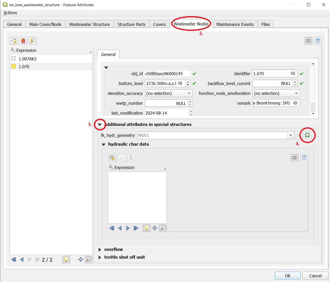
Select in layer vw_tww_wastewater_structure the wastewater structure with the i-button
Select the Wastewater Nodes tab in the Feature Attributes window
or in a more direct way: Select the node with the i-button in layer vw_wastewater_node
Expand the part ** additional attributes in special structures**
Select a hydr_geometry in the fk_hydr_geometry field or use the + button to create a new hydr_geometry.
For a new record: Enter a description in the hydr_geometry - Feature Attributes window. This name is also the name of the table in Mike+.
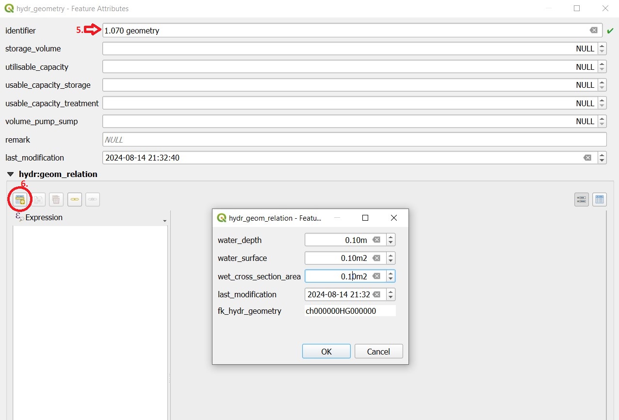
With the Add child object button, you can now generate the records with which the hydr_geometry is defined analogously to the basin geometry of Mike+ (H, As surface, Ac cross-sectional area).
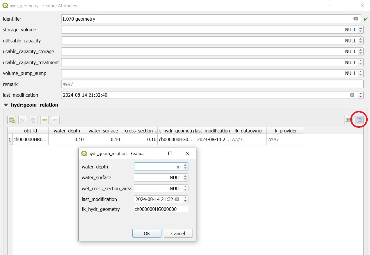
In the table view, the overview of the values is easier.
Note:
The water depth is the value above the bottom level or the outlet. A hydr_geometry can thus be used for several wastewater structure if they are built similar.
Be aware to respect the rules in Mike (e.g. continuous increasing cross_section_area)
As long as the hydr_geometry record is not saved, you see in the Features Attribute window just the Obj_Id in brackets. After saving, you will see the identifier you have entered.
Hydraulic modeling of an overflow (prank weir / leapingweir / pump)
There is a special view for overflows, altough it would be possible to edit the overflow-data in layer vw_tww_wastewater_structure. The advantage of layer vw_tww_overflow: overflows can be visualized, can be found again and are available in lists.
Action:
If it not already exists: In the case of weirs, a second wastewater node has to be created in the wastewater structure. A second outlet has already been created (green = discharged combined wastewater) and has not yet been linked to any wastewater node in the overflow structure.
Select the wastewater structure with the i-button
Select the wastewater nodes tab in the Feature Attributes window
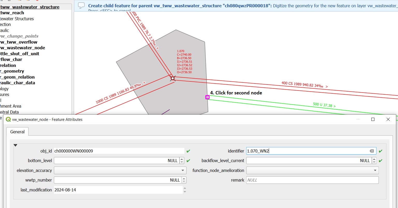
Create a second wastewater node with the Add point child object button. The light blue note at the top of the map tells you what to do!
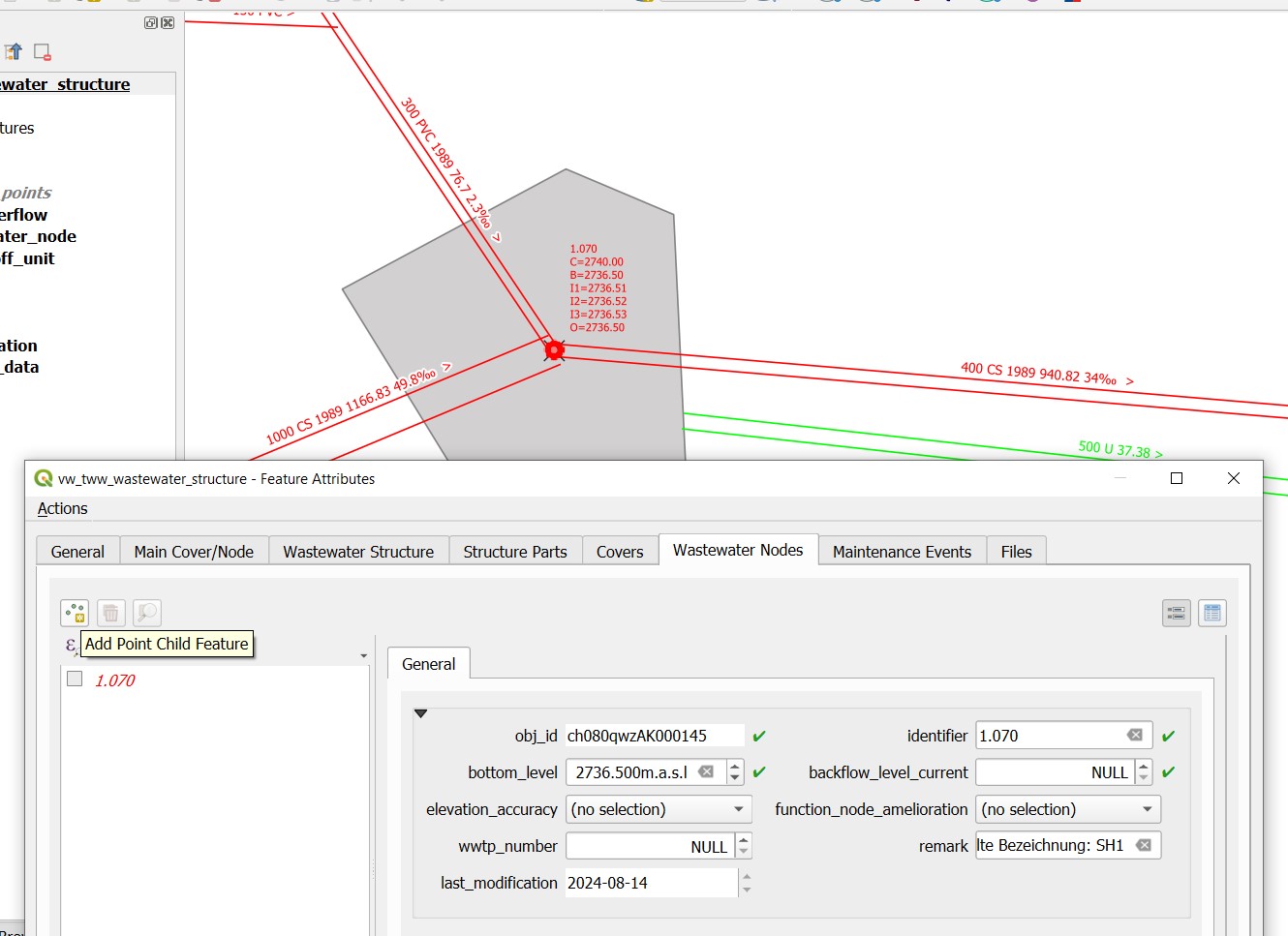
Click next to outlet 2 to place the second wastewater node.
The Feature Attributes window for this wastewater node appears. Enter a meaningful identifier (e.g. 1.070-WN2 for wastewater node 2 of the 1.070 special structure). This designation also appears in Mike+. The new wastewater node is saved with OK.
Close the Feature Attributes window of the wastewater structure.
To define a new prank weir:
Choose the layer vw_tww_overflow in the layergroup Hydraulic.
Choose the QGIS standard Add Point Feature button and click anyware near to the wastewater_structure
Hint
Because an overflow itself has no geometry, the place you click has no meaning. The geometry will be defined be the linked from- and to-wastewater nodes, see point 9
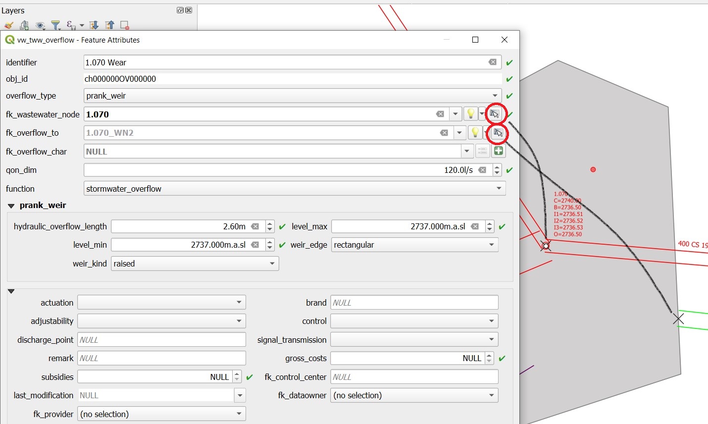
The overflow Feature Attributes window opens.
Enter an identifier and choose the overflow_type.
Define the two wastewater nodes of the overflow (fk_wastewater_node = from node, fk_overflow_to = to node) by selecting them on the map with the map identification-tool.
The attributes in the upper hydraulic section must be filled in, they will be transferred to Mike+.
Close all open Feature Attributes windows.
Hint
The new overflow is drawn as dotted line with arrow. If the line does not appear: the line is defined with the QGIS geometry generator symbol. Control the formula of the geometry generator (layer properties/symbology, select the symbol), control first the name of the vw_wastewater_node layer. If this layer is renamed, the formula has to be changed with the new name (e.g. vw_Abwasserknoten).
To finish, the 2nd outlet has to be linked to the 2nd wastewater node:
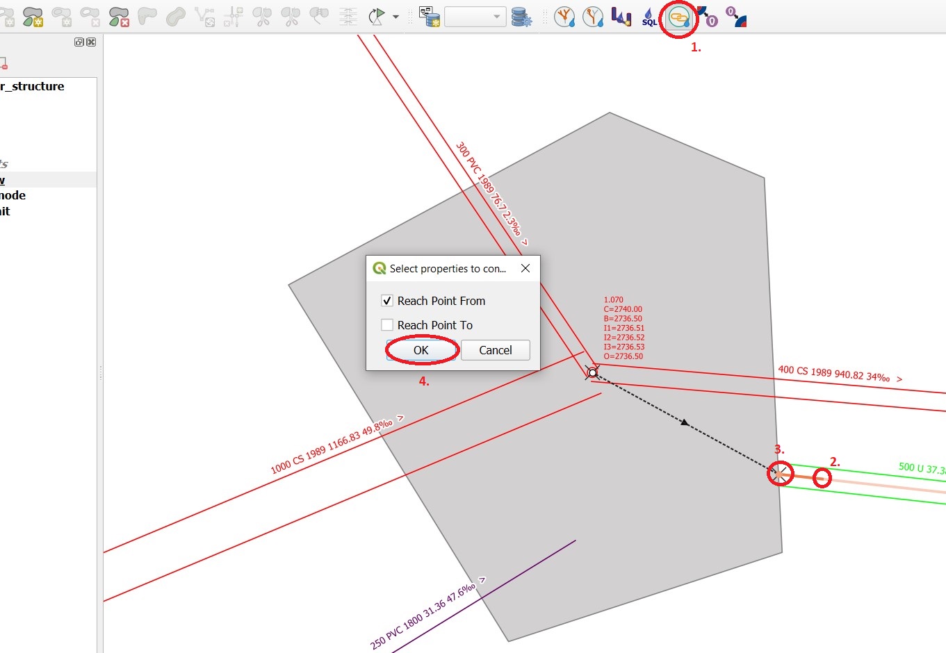
Select the TWW tool Connect wastewater networkelements.
Click on the reach near to the outlet
Click on the wastewater node
Confirm that the connection is created for the from reach point.
Overflow characteristic
In the case of a leaping weir, a pump or under special conditions, an overflow characteristic can be defined for the overflow:
You can select an existing characteristic in the field fk_overflow_char or you create a new characteristic with the green + button.
The Feature Attributes window for the overflow characteristic appears:
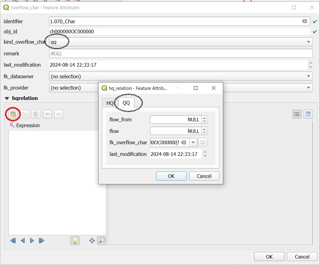
Here too, the identifer is later adopted in Mike+ as a table name for a QH relationship, which is used, for example, in a local controller.
Define the necessary HQ or QQ values with the add child object button. Be sure to choose the correct tab corresponding to the choice in kind_overflow_char
Further informations
Further Q & A’s you can find in the TWW Discussion section