Digitizing Channels
General
TWW has a wizard to correctly build channels and connect them to wastewater structures respectively to wastewater nodes or other reaches (building up the topology for waste water nodes and reaches). See the The TWW wizard chapter.
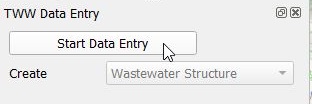
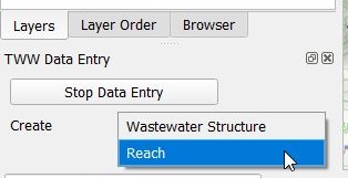
Select the Wizard button, then click Start Data Entry and choose Reach in the pull down menu.
Attention
Start digitizing in the direction of the flow by starting with the from manhole node and finishing with the to manhole node.
Digitizing
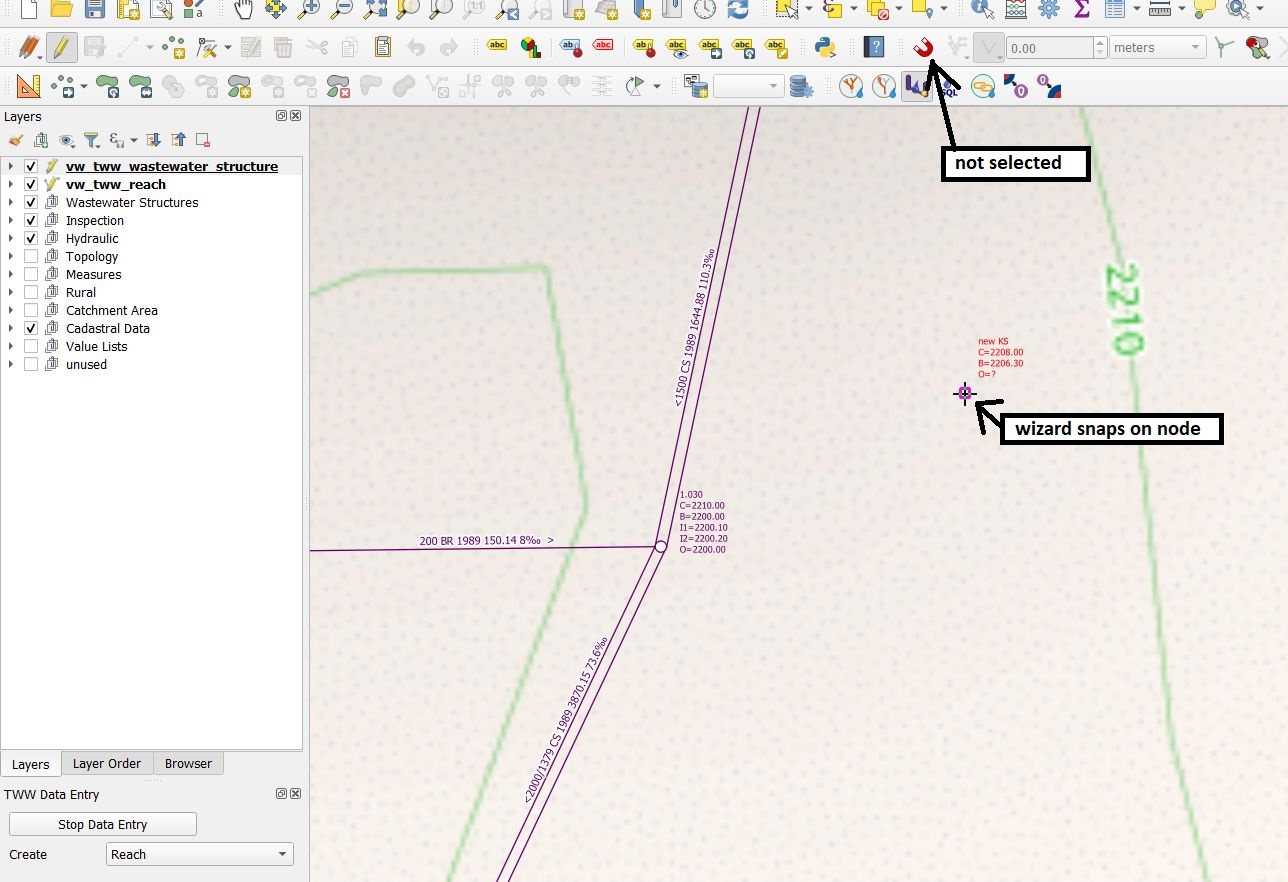
In digitizing mode the cursor will automatically snap to the nearest wastewater node or reach. When left clicking a line starts to draw.
With further left clicks anywhere you can define intermediary points of the reach progression. You can also directly select another manhole to draw a straight channel.
It is possible to use the Advanced Digitizing tools together with the wizard.

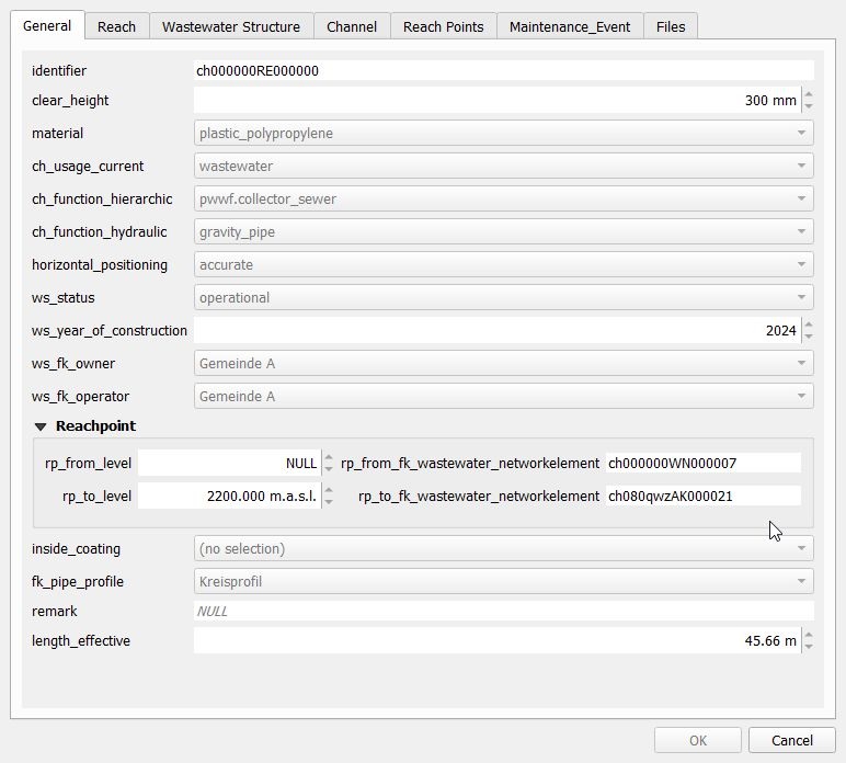
You finish digitizing the line by right clicking. This will make the vw_tww_reach feature attributes window appear and you can start adding data in the General tab:

Note
Keep in mind that the finishing point of the line is the last point where you left clicked. Thus, for digitizing a simple line with 2 points you need two left clicks to digitize the line and one right click to finish the line digitizing.
Control the snapping to wastewater nodes or other reaches in the fields rp_from/to_fk_wastewater_networkelement
Note
If you do not enter an identifier (reach-identifier) in the General tab, TWW will enter the obj_id also as identifier (you can change later). As default, the identifier of the reach is also the ws_identifier of the channel. As default, the reachpoint-identifier is set to the reachpoint-obj_id.
Note
See Geometry synchronization for automatic reachpoint levels when snapping to wastewater nodes with level.
For the profile type you will get a list of defined profiles. You can edit the pipe profiles in pipe_profile table (layergroup Wastewater Structures).

When finished, then click the OK button.
Save the information of this layer by stopping the data entry wizard.
Note
The standard-fields on the General tab (and only those fields) do reuse the last entered attribute value when you add new reaches with the wizard. The QGIS option Reuse the last entered attribute values and the default values have no influence on these fields.
You can re-edit your object selecting the edit mode and then click with the info cursor on the object you want to edit.
If you do not select the edit mode, you can just look at the existing data.
For detailed information about editing see the Editing of existing data chapter.
Further attributes and classes
When a line object is digitized, a series of steps take place in the background in the TWW database:
a new object is added in the wastewater structure class (
wastewater_structure)a new object is added and linked in the channel subclass (
channel)a new reach object is generated in the wastewater network elements class (
wastewater_networkelement) and its subclass reach (reach)two new reach point objects are added and linked to the reach (rp_from_node, rp_to_node)
Geometry synchronization
When inserting a new reach using the wizard, the start and end points of the line geometry determine the level of the corresponding reach points (as shown in the pictures above). These values can be overwritten before saving. Upon saving, the level values rp_from_level and rp_to_level are used to define the Z value of the first and last vertex of a reach.
When updating a reach, there are several cases:
The first/last reach geometry vertex was not changed, but the rp_from_level / rp_to_level was. In this case, the level value rp_from_level / rp_to_level is used to set the Z value of the first / last vertex of the reach
The first/last reach geometry vertex was changed, but the rp_from_level / rp_to_level was not. In this case, the QGIS variable @tww_update_lvl_by_geom defines whether the rp_from_level / rp_to_level is overwritten by the Z value of the first / last vertex of the reach
Both the first/last reach geometry vertex and the rp_from_level / rp_to_level were changed. The rp_from_level / rp_to_level take precendence
Neither the first/last reach geometry vertex nor the rp_from_level / rp_to_level was changed. No changes occur
Synchronization of levels works also for intermediate points (points between the reachpoints), if you snap while digitizing to 3d-points on another layer (e.g. a textfile as result of gps-measurement with x,y,z coordinates added to the QGIS-project). Be aware, that you have then a full 3d-reach, but on the export to INTERLIS these intermediate-levels will be lost, because VSA-DSS version 2020 does not support 3d for reach-geometry.
Digitizing flushing nozzle
Added in version 2025.0.
TWW is configured to digitize flushing nozzles as structure part of the channel.
You can digitize a flushing nozzle
starting on the Feature Attribut window of vw_tww_reach with tab Structure Parts. Add point child feature and digitize the point on the map. Or
create a new point on vw_flushing_nozzle and choose the connected channel for field fk_wastewater_structure on the map.
Note
A flushing nozzle is connected to a wastewater_structure, but it’s geometry is totally independent of the wastewater_structure-geometry. If you move the channel, you have to move the flushing nozzle manually.